Voltage Doubler Circuit Diagram
Voltage multiplier circuits with explanation Voltage doubler circuit wave half multiplier tripler diagram ac circuits switch two frequency circuitdigest way ripple pdf hz mains input Signals and systems: voltage doubler.
Voltage Multiplier and Voltage Doubler Circuit
Doubler 24v how2electronics What is a voltage double? definition, half wave voltage doubler, full Voltage doubler diode circuit rectifier wave current multiplier schematic half full dc tripler diagram doublers dubler hobby projects gif tutorial
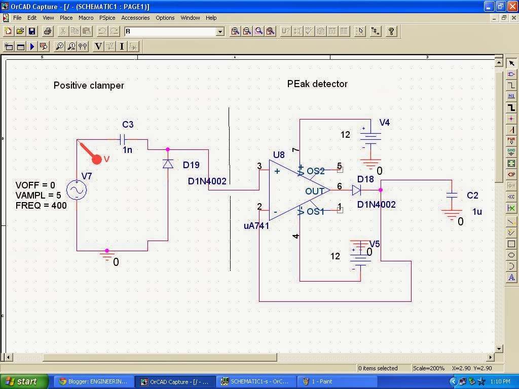
Cheap dc voltage doubler circuit
Voltage doubler wave circuit half diagram working rectifier capacitor figureCircuit voltage doubler diagram 555 ic timer capacitor frequency explanation circuitdigest astable circuits output discharge square 5v projects wave configured Voltage multiplier circuitsVoltage dc converter circuits doubler diagram circuit multiplier volts doubling redrawn conventional standard figure nutsvolts.
Voltage multiplier and voltage doubler circuitVoltage doubler circuit schematic ☑ diode voltage multiplier circuit12v to 24v voltage doubler circuit.

Voltage doubler dc xotic circuit diagram simple effects diagramz
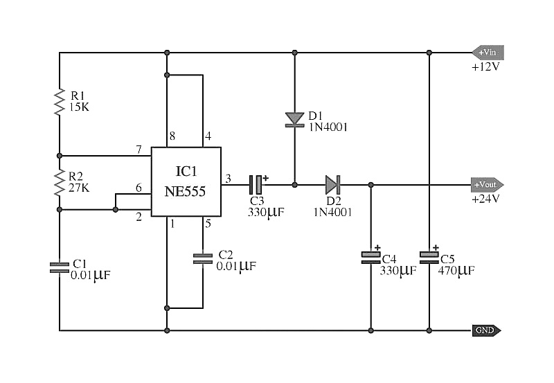
Voltage doubler circuit dc diagram wave full ac working schematic diode fullwave circuits simple supplyVoltage doubler circuit diagram and explanation Voltage ne555 doubler circuit schematic dc 12vdc circuits converter simple diagram timer boost shows 24vdc gr next volt will repositoryCircuit voltage doubler build breadboard.
☑ diode voltage doubler inverterDoubler voltage with ne555 schematic Simple dc voltage doubler circuit diagramFull wave voltage doubler circuit.

Circuit voltage doubler diagram seekic created higher charge diodes pump supply than
Voltage doubler multiplierVoltage doubler: what is it? (circuit diagram, full wave & half wave Voltage doubler circuit wave half two capacitors ac source hasVoltage doubler electrical4u.
Voltage doubler circuitDc voltage converter circuits How to build a voltage doubler circuitVoltage doubler circuit diagram and explanation.
(a) conventional and (b) proposed voltage doubler circuit.
12v to 24v voltage doubler circuitVoltage circuit doubler using timer ic breadboard diagram digest circuitdigest Voltage doubler conventional proposedVoltage doubler dc multiplier circuits diode working circuit bridge.
Voltage doubler tutorial and circuitsVoltage doubler 24v 12v power 1074 Voltage circuit doubler diode diagram triplerVoltage circuit multiplier diode doubler high wave microwave test gif.

Doubler schematic circuits elcircuit oscillator 10v 5v datasheet
Voltage multiplier circuitsDiode voltage doubler circuit with tripler and quadrupler explained Voltage doubler dc multiplier circuits diode eleccircuit supply conventionalVoltage doubler circuit here.
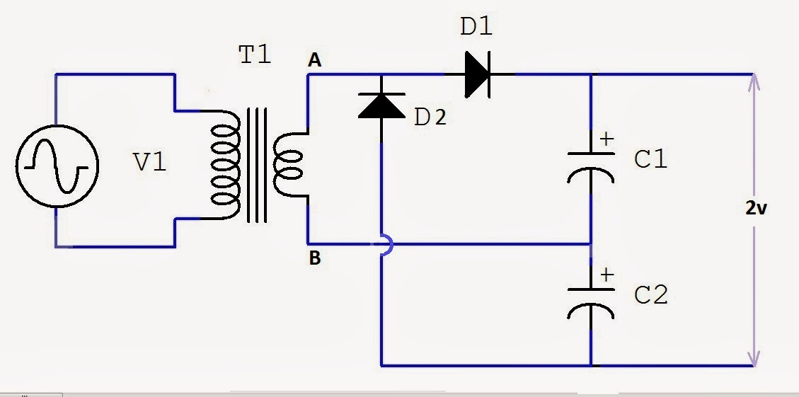
Voltage multiplier circuit doubler circuits wave half dc output ac provide known whichHalf-wave & full-wave voltage doubler: working & circuit diagram .


12V to 24V Voltage Doubler Circuit
Voltage Doubler Circuit schematic

Half-Wave & Full-Wave Voltage Doubler: Working & Circuit Diagram

How to Build a Voltage Doubler Circuit

DC Voltage Converter Circuits | Nuts & Volts Magazine

Voltage Multiplier and Voltage Doubler Circuit
Signals and Systems: Voltage Doubler.